Videos and report
Tuesday, December 11th, 2007Further development on the project stopped in February, 2007. But new video material has been uploaded by request.
Head for the videos section.
The report is available (in danish) here.
Further development on the project stopped in February, 2007. But new video material has been uploaded by request.
Head for the videos section.
The report is available (in danish) here.
We are currently in the process of testing the robot against many different human opponents.
So far it has beaten all opponents except one. All people describe their own skills within the range newbies-average, except the one opponent who calls himself “pro”.
Our initial goal with this project was beating a 7-year old, and since we have achived this and far more, we have stopped improving the AI for now, and are focusing on writing a report due 1. Feb.
Videos will follow…
With the christmas being done the work continues. We will mainly be working on our report from now on although minor improvements have to be made on the table. Click below for a preview of how the defense is handling right now.
http://video.google.com/videoplay?docid=-8074463179784059660It should stand a chance against newbies.
The powersupply we use cannot supply the whole table, but at most a single rod.
We measured the current at a single motor running full speed to 10A, which means we need to buy a bigger powersupply.
Right now we are running with 2×10 amps and 1×20 amps supplies.
To test wether the circuit would burnout from a sidecrash, now that greater currents are available, a full speed sidecrash was tested (see video).

The board stall detection system worked like a charm, but the timing belt was strained so much that it snapped eventually. The conclusion is, the board wont burn-out in case of an error, but timing belts (at least the old ones) will snap, either way, this was probably the last full speed side crash test we will ever do.
The objective of the reset procedure is to locate the moving range for the rod. This is done by moving the rod as far as possible to one side. Earlier this was done using the rod switches. They have been removed, and the motor-controller detects the end purely using software now.
The rod moves slowly, because it is expecting a crash with the side, to calibrate for zero (see video).

During the last few weeks a new motor-controller software was implemented and tested.
The new motor-controller software detects when something is preventing the rods from moving, ie. when the remains of a child’s hand has gotten caught in the mechanics. Rather than continuing the molesting, the rod stops after 0.2 seconds of stalling.
This is also relevant if the rods should move too far sideways. Instead of a circuit burn off, the doubling of current happens for 0.2 seconds, before the board cuts the power. The following video demonstrates rod sideways movement and in the end a sidecrash. The LED indicates the power has been cut.
This also happends should the ball get stuck between a shooting man and the floor:
This has been implemented in the following way:
If the rod hasn’t moved for 0.2 seconds and the wanted position isn’t the current position, go into emergency stall mode.
This emergency stall mode has to be exited by a hard reset or a soft reset sent by the server controlling the motor-controller boards, before the motor-controller responds to any set position calls.
To prevent a rod from moving too far sideways. Two switches are located at each rod. These are supposed to be hit whenever a rod moves too far. But these switches are attached with double tape, and have a tendency of falling off. It is a problem mounting them properly, because for them to be effective without being a limitation, they have to be placed with great precision, and holes have to be drilled.
Since the switches fall off, we had an accident with one of the rods moving too far, resulting in a burned out circuit on one of the motor-controller boards. The rod had moved to the end of the possible moving range for the rod, and the engine was still fully powered, resulting in doubling of the current for about 2-3 seconds.
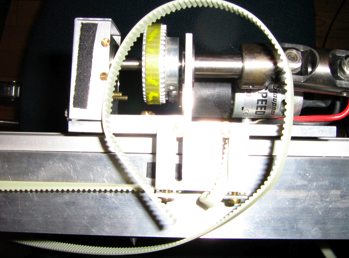
Also in seperate incident, a timing belt snapped (see picture). Unfortunately, they are old and have lost their flexibility.

They aren’t steelwire enforced, so should the problem reoccur, stellwire enforced timing belts would make good substitutes.
Instead of mounting the switches properly, we’ve decided to create a software fix, and remove them entirely, more on this later.
A number of improvements have been made to the imaging software.Â
Using almost hardcoded values for the position of rods in the picture, the position of the human men on the rods can now be found. For each rod the algorithm works by starting to look at the rod from one end and progressing towards the other, pixel by pixel. In each pixel row it measures the number of pixels that look like a man. Then a weighted average of these values is made to find the actual position of the man.
The ball finding algorithm now uses a weighted average of the color values in each pixel to find the exact position of the ball. This should give sub pixel precision but measurements of the variance in the found position with and without a weighted average should be made.
When playing, the camera shakes back and forth. To compensate for this when trying to find the ball and men, we have made an antishaking algorithm that continually looks at one edge of the table. When this edge moves the antishaker changes the corner pixels of the table accordingly.
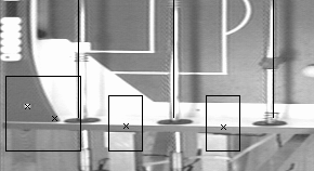
On the calibration picture you can see where the program has found the white sticker in the corner, where it thinks the corner of the actual playing field is, where it thinks the rods are and where it finds the edge of the table (for the antishaker).

The big black box shows the area within it looks for the white sticker. The smaller black boxes indicate where the antishaker looks for the white to dark transition and thereby the table border.